Specifications
MSO-9201
MSO-9212
MSO-9201
w/LAPOD
Timebase
500 MSa/s... 5Sa/s
2 ns / sample to 5s/sample
2 ns / division to 20s / division
External rising
External falling
External rising and falling
1 GSa/s... 5Sa/s
(1 GSa/s mode is only available in single channel mode)
1 ns / sample to 5s / sample
1 ns / division to 20s / division
External rising
External falling
External rising and falling
500 MSa/s... 5Sa/s
2 ns / sample to 5s/sample
2 ns / division to 20s / division
External rising
External falling
External rising and falling
Rate (single shot)
20 GSa/s...1 GSa/s
50 GSa/s...1 GSa/s
20 GSa/s...1 GSa/s
Rate (Repetitive)
2 ns
1 ns
2 ns
Resolution
+/- 0.01%
Accuracy
< 2 ns
Skew
Inputs
2
2
2
DSO channels
0
12
12
Logic Analyzer channels
Oscilloscope
200 MHz
Bandwidth
BNC or Probe (1X)
Voltage per division: 5 mV to 2 V
Full scale voltage: 50 mV to 20 V
Probe (10X)
Voltage per division: 50 mV to 20 V
Full scale voltage: 500 mV to 200 V
Probe (100X)
Voltage per division: 500 mV to 200 V
Full scale voltage: 5,000 mV to 2,000 V
Gain Range
(per division)
full scale = 10 divisions
BNC or Probe (1X)
Continuous: ± 50 V DC
Transient: ± 100 V DC
Probe (10X)
Continuous: ± 500 V DC
Transient: ± 1,000 V DC
Probe (100X)
Continuous: ± 5,000 V DC
Transient: ± 10,000 V DC
Max Input Voltage
max input voltage at probe tip
depends on probe type
(1x, 10x, 100x, etc)
8 bits/ch
Vertical Resolution
10 divisions
Vertical Range
± 5 divisions
Offset Range
0.04 division increments
Offset Resolution
AC, DC and Ground
Coupling
1 MΩ // 15pF
Impedance
± 2%
DC Accuracy
Dual 8 bit
ADC
Logic Analyzer (Digital)
100K ohm || 2pF
Impedance
<500 mV
Sensitivity
± 50 V DC (±100 V DC transient)
Max. input voltage
150 MHz
Bandwidth
+6V to -2V(Adjustable in 0.1 V increments)
Threshold voltage
Memory
512 Kpt
(512 thousand points/channel)
2 Mpt
(2 Million points/channel)
512 Kpt
(512 thousand points/channel)
Buffer size
Trigger
Rising Edge (Adjustable level),
Falling Edge (Adjustable level),
Pulse Width & Pulse Count
Window outside
Rising Edge (Adjustable level),
Falling Edge (Adjustable level),
Pulse Width & Pulse Count
Window outside
I2C
SPI
12 bit wide Logic Analyzer
Rising Edge (Adjustable level),
Falling Edge (Adjustable level),
Pulse Width & Pulse Count
Window outside
I2C
SPI
12 bit wide Logic Analyzer
Type
Any of the digital inputs can be used as an external trigger
External trigger input
Yes
External trigger output
Auto, Normal and Single
Mode
Yes
Autosetup
10 divisions
Range (vertical)
0.04 division increments
Resolution
Software
Yes
Windows
Yes
Spectrum Analysis/FFT
Yes
XY Plot
Yes
Math
Yes
Advanced Math
Yes
Data Logging
(based on pass/fail test)
(on every capture)
Yes
Physical
USB
Interface
Two 300 MHz 1x/10x switchable probes.
Two 300 MHz 1x/10x switchable probes, LA wire harness and 16 LA clips are included.
Two 300 MHz 1x/10x switchable probes, LA wire harness and 16 LA clips are included.
Probes
BNC: 3 total: 2 input and trig-out
LA Pod: 12
USB
Power: 12V 1A input
Connectors
Yes
Calibration point
12 V at 1 A (Typical)
The MSO ships with a power supply rated from 100-240 V and 47-63 Hz. It has a U.S. style wall connector. International customers will need a plug conversion adapter
Power Requirement
Main unit: 7.9" x 4.7" x 1.5"
Power supply: 2.1" x 1.8" x 1.0"
Main unit: 7.9" x 4.7" x 1.5"
Logic pod: 4.25" x 3.87" x 0.87"
Power supply: 2.1" x 1.8" x 1.0"
Main unit: 7.9" x 4.7" x 1.5"
Logic pod: 4.25" x 3.87" x 0.87"
Power supply: 2.1" x 1.8" x 1.0"
Dimenstions
MSO-9201
$950MSO-9201 w/LA
$950MSO-9201 Mixed Signal Oscilloscope
The MSO-9201 Mixed Signal Oscilloscope combines the features of a digital oscilloscope and a logic analyzer in an integrated, easy-to-use package. The instrument offers 500 MSa/s for single shot sampling and 20 GSa/s for repetitive signals. The MSO-9201 has 14 channels: 2 digital storage oscilloscope channels and 12 logic analyzer channels . All channels are fully synchronized and can each store up to 512 Kpt. The MSO-9201 has advanced triggering with options, such as: Rising/Falling edge, pulse width and count, 12 bit Logic, I2C and SPI. The scope is portable and connects to a PC via USB. The advantage of an MSO is having time-aligned analog and digital inputs displayed on the same screen, so having one instrument is more powerful than two separate instruments. Gain more insight into your circuits.
- History plots (variable persistence with color)
review and compare current and previous captures - XY Plot
- Data averaging for increased accuracy
- Auto-setup
- Fast, accurate measurement
- Data storage with save and export capabilities
- Automatic storage
File save and export capabilities
Datalog each capture
Datalog for pass/fail measurement - Simple operation
- External clock input
An exceptional feature for an oscilloscope
Synchronize sampling to an external source - FrontPanel® Oscilloscope software supports Windows
- DLL libraries (optional)
- Inputs: 2 x DSO + 12 x LA
- High speed sampling
Single shot: 500 MSa/s
Repetitive mode: 20 GSa/s
Bandwidth: 200 MHz - Large capture buffer
512 samples per channel - USB Communication
- Advanced triggering
Level / Edge
Glitch
Pulse width & count
12 bit Logic Analyzer
SPI
I2C - SPI and I2C decoding
- 500 MHz Spectrum Analyzer / FFT
Overview
All 14 channels are sampled simultaneously and displayed together. Analog and digital waveforms are acquired with the same sample clock to assure accurate time correlation between the two. Even by cabling two individual instruments together, one would still not be able to obtain samples within 2 ns of each other, and the triggering would not be as tightly coupled as with a single unit.
MSO-9201: Time-Synchronized Oscilloscope and Logic Analyzer Inputs
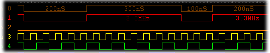
The Logic Analyzer display can show individual pulse width and frequency information.
The MSO-9201 has an external clock input that is primarily used when doing logic analysis, but is also useful when doing mixed signal analysis or even pure DSO work. With an analog bandwidth of 200 MHz and 20 GSa/s, the MSO-9201 is the new performance leader in its price range. By fully utilizing high-speed USB communications and size-changeable acquisition buffers, the MSO-9201 can be adjusted to provide fast screen updates and a very responsive analog oscilloscope-like experience.
The MSO-9201wLA also has an external clock input that is primarily used when doing logic analysis, but is also useful when doing mixed signal analysis or even pure DSO work.
Fast 500 MSa/s ADCs allow the MSO-9201 to acquire and resolve events as narrow as 1 ns. The MSO can simultaneously sample at 500 MSa/S (2 ns) across all 14 inputs (2 DSO+12LA). 20 GSa/s (50 pS) sampling resolution is available in RIS (Random Interleave Sampling) mode. On the opposite end of the timebase spectrum, the MSO can sample at 1 Sa/S, which equates to 524,288 seconds, over 145 hours, or 6 days per acquisition.
High-Speed Sampling
"The big buffer really saved me. With my last oscilloscope I always had to balance recording time and time per division. With Link's scope I can record at the fast sampling rate and still see the entire event." Bob Mitchell, consultant. (Beta Tester)
A vast amount of data can be captured in the large acquisition buffer. The 512 Kpt buffer allows for high-speed samples and captures of long traces. Other instruments with short memory buffers force you to degrade your sample rate and thus lower your bandwidth. For example, if you needed to capture a 100 us event using a 500 MSa/s scope with a 2.5k buffer, you would reduce your sample rate to 20 MSa/s, or at best a bandwidth of 5 MHz! The MSO-9201 would let you view that 100 us event at 5 GSa/s.
Deep Acquisition Memory
This example shows use of FFT averaging to identify and reduce noise.
The dual channel FFT has controls for FFT windows, FFT types, FFT resolutions, frequency range filters, peak holds, and Min/max envelopes.
The software also supports averaging, memory, and plot subtraction. This allows for a whole range of spectral analysis including: frequency response analysis, power supply noise analysis, etc.
FFT data can be saved to a disk and exported to other programs such as Excel, Mathcad, etc.
Spectrum Analyzer / FFT
- XY Area (Lissajous curve)
- Angle
- Delta X
- Radius
- Delta Y
XY Oscilloscope Plot
A powerful suite of over 40 measurements is available. The measurements can be performed on an incoming waveform, a stored waveform or a mathematically processed waveform. The data cursors can be used to define a subset of data to be measured.
Waveform Measurements
The MSO-9201wLA can display and decode SPI bus protocols as well as trigger on them. Up to 3 SPI buses can be decoded simultaneously. SPI decode window.
SPI Decoding
Decoded SPI data and timing waveform display.
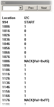
The MSO-9201wLA can display and decode I2C serial bus protocols as well as trigger on them. I2C signals can also be viewed as timing waveforms or in a statelist-style display.
I2C Decoding
- Perform sophisticated operations that cannot be done with a knob-based DSO.
- Save default setups to disk for easy recall at a future date.
- Screen shots can be pasted into documents and annotated in a preferred image-editing program.
- lnstallation is a snap.
- Make measurements in no time.
- Simple controls make operation intuitive.
Simple Operation
Trace data can be averaged over many captures to reduce noise and increase accuracy. The average can be saved to memory, logged to disk or reset after a specific number of captures.
Data Averaging for Increased Accuracy
To save time, waveforms can be automatically datalogged to a PC. Data can be stored after each capture or according to the results of pulse measurements.
Automatic storage
The instrument has high-speed samplers and buffers. It can acquire information at up to 1 GSa/s and stores the data in its own two MegaSample data buffers. When these buffers are full, the data is transferred to the PC.
All of the high-speed acquisition is done with the MSO hardware; the speed of a PC is not a factor. The PC is simply used for the display and user interface. If a PC is fast enough and has enough memory to run Windows well, it will also run our products well.
PC Speed Does Not Significantly Affect the Performance of Our Instruments
The optional DLL library allows users to write custom software to control the instrument. The library works with Visual Studio, LabView and Matlab.
Software Libraries
The oscilloscope can automatically save and display up to 30 previous captures. Each capture will be color-coded, and the oldest ones will fade away.
In this shot, the blue trace represents the current capture. The yellow traces are the 30 most recent captures. The older history traces fade to black.
Channel History is Better Than Persistence Mode.
One of the benefits of pulse width triggering is that it can detect glitches. Digital domain triggering can use either a 12-bit wide digital word or the advanced serial trigger (I2C and SPI bus protocols).
The MSO-9201 w/LA can trigger on a signal in either the digital or analog domain. In the analog domain, triggering can be done using a rising or falling edge. Other analog domain triggering features are pulse width and pulse count.
Cross Triggering
In this example, four timing windows are being displayed: Window 1 shows the entire buffer; Window 2 shows a zoomed in section around the trigger (red cursor) event; Windows 3 and 4 show a unique part of the waveform and are zoomed differently.
There are often many points of interest that are scattered throughout the buffer.
QuadVue® provides four independent timing windows that allow users to view the entire buffer while simultaneously focusing on details, so there is no need to constantly pan and zoom.
Each window can display a unique timebase while showing any or all channels.
For quick analysis, one can superimpose the current data over the mathematically operated and history memory data.
QuadVue® Display
Stand-alone oscilloscope display screens represent a compromise at best. Few people would choose a 7" or 9" monitor as the screen for their PC. So why use a small monitor for an oscilloscope? Our software will also work with dual-monitor PCs. Imagine having a 30" wide trace window!