Specifications
Timebase
200 MSa/s... 100Sa/s
5 ns / sample to 10ms/sample
50 ns / division to 100ms / division
Rate (single shot)
2 GSa/s and 1GSa/s
5 ns/division to 100ns/division
Rate (Repetitive)
+/- 0.01%
Accuracy
5 ns
Resolution
< 5 ns
Skew
Inputs
2
DSO channels
8
Logic Analyzer channels
Oscilloscope
60 MHz
Bandwidth
BNC or Probe (1X)
Voltage per division: 5 mV to 500 mV
Full scale voltage: 40 mV to 4 V
Probe (10X)
Voltage per division: 50 mV to 5 V
Full scale voltage: 400 mV to 40 V
Gain Range
(per division)
full scale = 8 divisions
BNC or Probe (1X)
Continuous: ± 20 V DC
Probe (10X)
Continuous: ± 200 V DC
Max Input Voltage
max input voltage at probe tip
depends on probe type
(1x, 10x, 100x, etc)
8 divisions
Vertical Range
± 4 divisions
Offset Range
12.5 mV
Offset Resolution
AC and DC
Coupling
1 MΩ // 15pF
Impedance
± 2%
DC Accuracy
Yes
Memory Channel
Logic Analyzer (Digital)
100K ohm || 2pF
Impedance
<500 mV
Sensitivity
+ 5.5V DC
Max. input voltage
100 MHz
Bandwidth
0.6V to 1.65 V (1.2, 1.5, 1.8,2.5,3.0, 3.3, 5.0 V Logic Families)
Threshold voltage
Yes
Memory channels
SPI
Yes, 32 bit wide trigger word, Mode 0..3 supported
Trigger
Yes
Decoding window
I2C
Yes, 32 bit wide trigger word
Trigger
Yes
Decoding window
Spectrum Analyzer (FFT)
0..100 MHz (with 3dB roll-off at 60 MHz)
Frequency range
0.098Hz to 195KHz depending on frequency range setting
Resolution
Rectangular, Tapered Rectangular, Triangular, Hamming, Hanning, Flat top and Blackman-Harris
Window
Magnitude, Power Spectrum, Power Density, Real and Imaginary
Plot
Vertical and Horizontal
Zoom
Yes
Memory channel
Yes
Averaging channel
2
Cursors and Measurements
Memory
1000 points/channel
Buffer size
Trigger
Rising Edge (Adjustable level),
Falling Edge (Adjustable level),
Pulse Width
8 bit wide Logic Analyzer
I2C
SPI
Type
Any of the digital inputs can be used as an external trigger
External trigger input
Yes
External trigger output
Auto, Normal and Single
Mode
Yes
Autosetup
8 divisions
Range (vertical)
12.5 mV
Resolution
Software
Yes
Windows,
Linux,
Mac
Yes
Spectrum Analysis/FFT
Yes
Measurements
Yes
Physical
USB
Interface
Two 1x/10x switchable probes, LA wire harness and 9 clips are included.
Probes
BNC: 2
Logic Analyzer/Pattern Generator: 8
USB
Connectors
Yes
Calibration point
USB powered
Power Requirement
4.0" x 2.4" x 0.8" (102mm x 61 mm x 20 mm)
2.5oz. (70g) (MSO only)
Shipping box: 9" x 6" x 2"
Shipping weight: 14oz.
Dimenstions
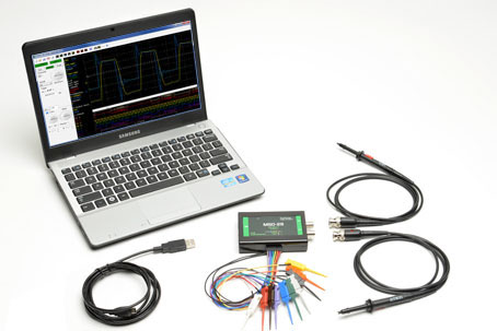
MSO-28 Oscilloscope, Logic Analyzer, Spectrum Analyzer
The compact MSO-28 operates as both a 2 GSa/s Oscilloscope and a 200 MSa/s Logic Analyzer. All channels sample simultaneously at a max rate of 200 MSa/s.
At only $325, the MSO-28 includes probes, clips, wires, and software. It connects to any PC via USB. Being USB powered means, no external power supply is necessary.
Following the successful deployment of the MSO-19 on the International Space Station (ISS), the MSO-28 was delivered to the ISS via Orbital Science's ORB2 mission to join the MSO-19 in expanding the debugging capabilities of astronauts on the ISS.
The MSO-28 appeals to a large audience, including:
- Engineers who need a 2GSa/s Mixed Signal Oscilloscope
- Students
- Hobbyists
- Field service technicians
- Field application engineers
- Consumers who need a small travel scope or logic analyzer
- Those who require a powerful trigger box to use with other instruments
- Advanced triggering
Level / Edge
Glitch
Pulse width
8 bit Logic Analyzer
SPI
I2C - SPI and I2C decoding
- Simple operation
- FrontPanel® Oscilloscope software supports Windows
- DLL libraries (optional)
- Inputs: 2 x DSO + 8 x LA
- High speed sampling
Single shot: 200 MSa/s
Repetitive mode: 2 GSa/s
Bandwidth: 60 MHz - USB Communication and USB powered
- Autosetup
- Fast, accurate measurement
- 100 MHz Spectrum Analyzer / FFT
- Data storage with save and export capabilities
Overview
All 10 channels are sampled at the same time and displayed together. This is better than using multiple separate instruments because the analog and digital waveforms are acquired with the same sample clock, assuring accurate time correlation between the two. Even through cabling two individual instruments together, samples would not be within 5 ns of each other, and the triggering would not be as tightly coupled as it would be with a single instrument.
Since the software displays the oscilloscope and logic analyzer data on the same screen, it stays synchronized no matter how much a user scrolls or zooms.
MSO-28: Time-Synchronized Oscilloscope and Logic Analyzer Inputs
The Logic Analyzer display can show individual pulse width and frequency information.
Triggering options include:
- Trigger level rising edge
- Trigger level falling edge
- Pulse width
- 8 bit Logic Analyzer
- SPI
- I2C
The MSO-28 can trigger on the Oscilloscope, Logic Analyzer, SPI or I2C inputs. All 10 inputs sample at the same time, and they are displayed together. The external trigger can be used to output to trigger other instruments.
Advanced Triggering
High-speed sampling is key to getting a good capture. An accurate capture of a 60 MHz signal can be obtained with the 200 MSa/s single shot sample rate and 60 MHz bandwidth. With RIS mode sampling, one can capture even faster signals.
HIgh-Speed Sampling
This example shows use of FFT averaging to identify and reduce noise.
The FFT Spectrum Analyzer has controls for FFT window, FFT type, and FFT resolution.
The software also supports averaging, memory, and plot subtraction. This allows for a whole range of spectral analysis, including: frequency response analysis, power supply noise analysis, etc.
The maximum FFT frequency analysis is 100 MHz.
FFT data can be saved to disk and exported to other programs such as Excel, Mathcad, etc.
Spectrum Analyzer / FFT
tandard waveform measurements are included and can be displayed on the screen right next to the traces.
Measurement results can be saved with the data files
Waveform Measurements
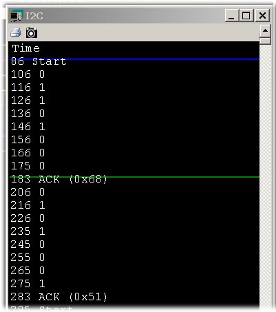
The MSO-28 can display and decode SPI and I2C serial bus protocols as well as trigger on them. SPI and I2C signals can also be viewed as timing waveforms and statelist-style displays.
SPI and I2C Decoding
- Perform sophisticated operations that cannot be done with a knob-based DSO.
- Save default setups to disk for easy recall at a future date.
- Screen shots can be pasted into documents and annotated in a preferred image-editing program.
- Fast installation.
- Quick measurements.
- Simple controls make operation intuitive.
Simple Operation
- Data can be exported in "CSV" format to programs like Matlab, Excel, Word, etc.
- Users can paste screen images into their reports using programs like Word, Excel, image editors, etc.
- Data can even be shared with other computers. One can capture data in the lab and view it in your office or e-mail it to other engineers at remote locations for analysis. There is no need to be connected to our instrument in order to view a file.
Data Storage
Stand-alone oscilloscope display screens represent a compromise at best. Few people would choose a 7" or 9" monitor as the screen for their PC. So why use a small monitor for an oscilloscope? Our software will also work with dual-monitor PCs. Imagine having a 30" wide trace window!
Link's Windows-Based Oscilloscope Software Takes Advantage of a Computer's Large Color Screen
The instrument has high-speed samplers and buffers. It can acquire information at up to 200 MSa/s and stores the data in its own internal data buffers. When these buffers are full, the data is transferred to the PC.
All of the high-speed acquisition is done with the MSO hardware; the speed of a PC is not a factor. The PC is simply used for the display and user interface. If a PC is fast enough and has enough memory to run Windows well, it will also run our products well.
